I love digital logic. I love solving digital logic conundrums. And I especially love discovering interesting and unusual ways of doing things while also learning more about the people who came up with these ideas in the first place. Take Gray codes, for example. These were named after Frank Gray, who was a physicist and researcher at Bell Labs.
The Gray code, or reflected binary code (RBC), which first appeared in a 1953 patent, is a binary numeral system that is often used in electronics, but that also has many applications in mathematics. Consider a 3-bit binary count sequence: 000, 001, 010, 011, 100, 101, 110, 111, and back to 000. In this case, some transitions involve multiple bits changing at the same time. For example, the transition from 001 to 010 involves two bits changing simultaneously, while 011 to 100 involves all three bits changing.
By comparison, consider a 3-bit Gray code sequence: 000, 001, 011, 010, 110, 111, 101, 100, and back to 000. In this case, adjacent values always differ by only 1 bit.
The idea is simple enough… once someone shows it to you. I don’t know about you, but—if left to my own devices—I don’t think I would have come up with this in a thousand years.
As an aside (I’ve mentioned this before, but some readers may be new to this column), one of my favorite logic puzzles involves a black box with three inputs (A, B, C) and three outputs (NotA, NotB, NotC).

The three outputs are the logical inversions of their corresponding inputs. That is, when A is 0, NotA is 1; when A is 1, NotA is 0; when B is 0, NotB is 1, and so forth.
Your mission is to come with a set of logic gates that will provide the desired function using only two NOT gates along with as many AND and OR gates as you wish, but no other inverting functions like NAND, NOR, XOR, or XNOR gates.
Although this may seem impossible at first glance, it can indeed be solved without any trickery or skullduggery. The various solution(s) are awesome. My favorite is presented in my Mysteries of the Ancients: Binary Coded Decimal (BCD) column.
Recently, I set myself a task of driving ten 7-segment displays using as few as possible (with a maximum of 12) digital input/output (I/O) pins on an Arduino Uno augmented by as few supporting chips as possible.
Why this particular task? Well, it arose as part of an educational series I’m working on to teach beginners about electronics in general and Arduinos in particular. Why use an Uno? I like the challenge of creating code for an 8-bit machine running at 16MHz with only 2KB of RAM.
And why only 12 digital I/Os? Well, the Arduino has 14 digital I/O pins, which are numbered from 0 to 13, but I’m reserving pins 0 and 1 for serial (UART) communications with my host PC. It also has six analog input pins that can also be used as digital I/Os, but I’m reserving those for other purposes.
I’m using 10-pin single digit common cathode 7-segment displays. Note that the “7-segment” portion of the moniker refers to the seven rectangular-ish elements used to display the digits; there’s also an eighth element that can be used to represent a decimal point (DP).
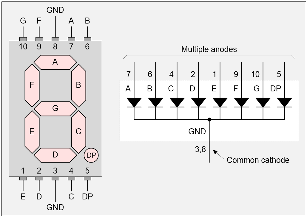
Segment names and pin numbers for 7-Segment display (Source: Max Maxfield)
Let’s start with a single display. The easiest way to control this is to use the Arduino’s pins to drive the display’s pins directly (via current-limiting resistors, of course).
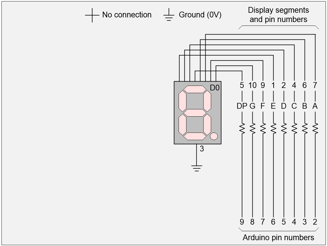 1 display, 8 Arduino pins (Source: Max Maxfield)
So far, so good, but what if we want to drive more displays. Using this “direct drive” approach, two displays would require 16 Arduino pins, but we have only 12 at our disposal. One thing we could do would be to multiplex the displays as shown below.
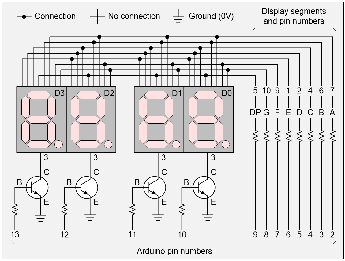
4 displays, 12 Arduino pins (Source: Max Maxfield)
The idea is that we start by using the Arduino to turn all the transistors off. Then we set the required 0 and 1 values on the pins driving the segments. Then we turn one of the transistors on to activate its associated display. We display the value for a short time (say 1/1000 of a second), then we turn that transistor off again. We repeat the process with different values for the other three displays
By cycling through the displays quickly enough, activating and deactivating them in turn, our “persistence of vision” makes it appear as though all the displays are active at the same time.
With respect to Arduino pins 13, 12, 11, and 12, we are cycling through the following four patterns: 0001, 0010, 0100, 1000, and back to 0001 again.
The problem is that we’ve now maxed-out our 12 pins. One way to free up some pins would be to use a 2:1 decoder. In this case, we could use two of the Arduino’s pins (say 11 and 10) to cycle through four binary combinations, 00, 01, 10, 11 and back to 00 again. Our 2:4 decoder can take these patterns and translate them into the 0001, 0010, 0100, 1000 equivalents we require to drive our transistors as illustrated below.
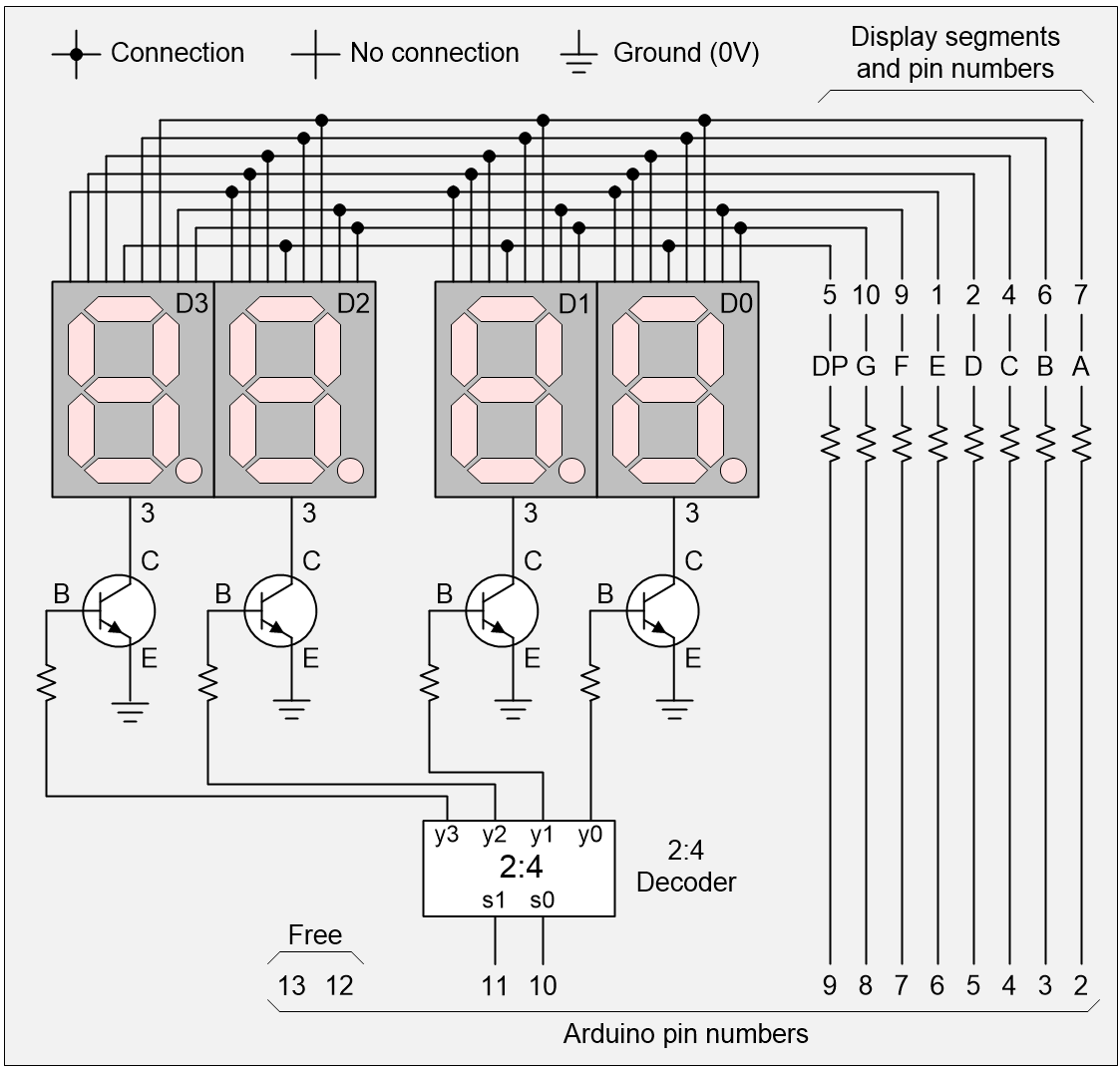
4 displays, 10 Arduino pins (Source: Max Maxfield)
We could use a similar approach to extend the number of displays. For example, we could use a 3:8 decoder to drive 8 displays, but this would leave us with only 1 pin free. Similarly, we could use a 4:16 decoder to drive up to 16 displays, thereby meeting or exceeding our goal of 10 displays, but this would once again consume all our pins as illustrated below.
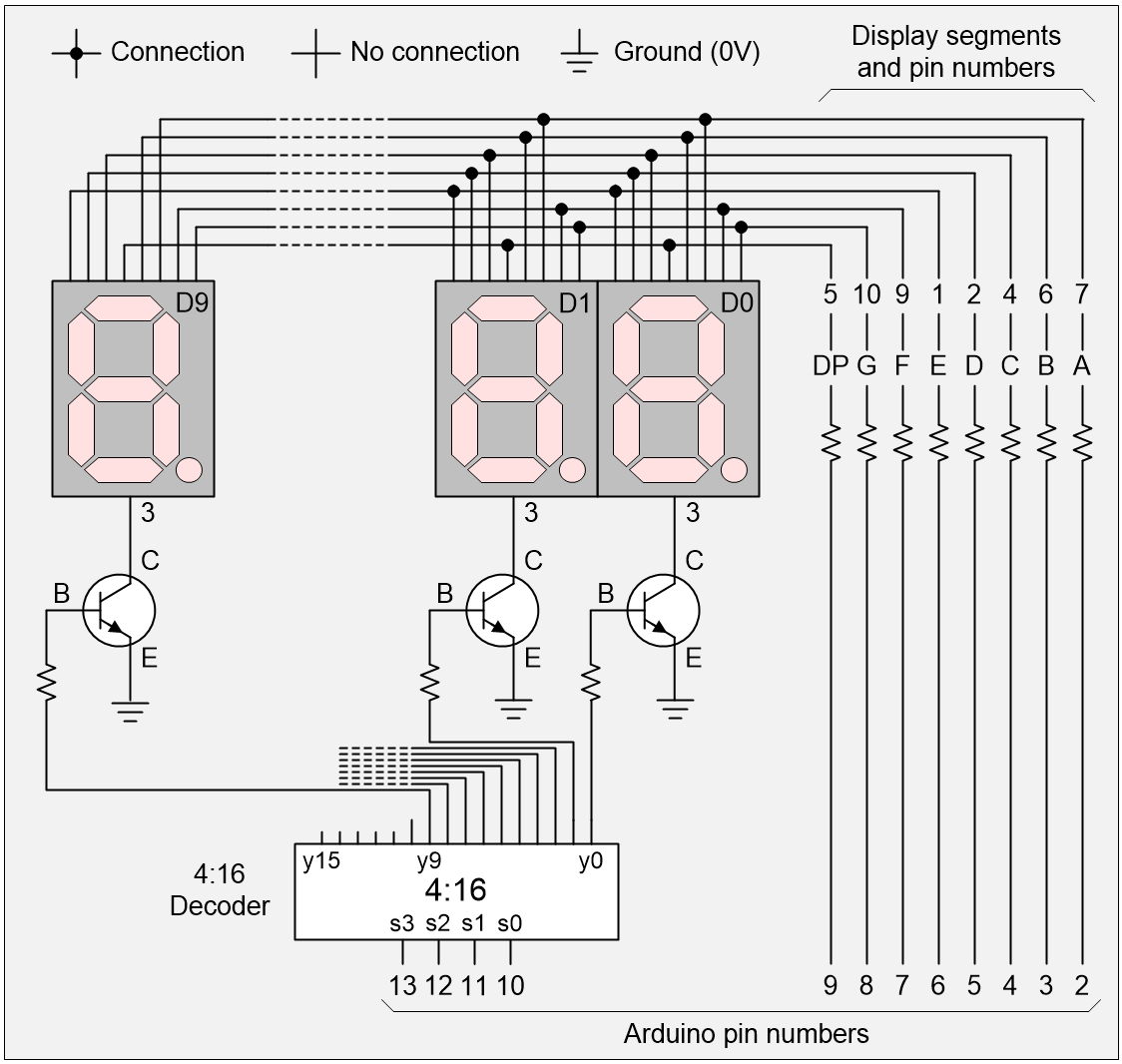
10 displays, 12 Arduino pins (Source: Max Maxfield)
Of course, one way we could easily free up four more pins would be to add a BCD-to-7-segment decoder as illustrated below. The main downside to this is that we would lose the ability to control our displays’ DP segments, but that’s something we could worry about later.
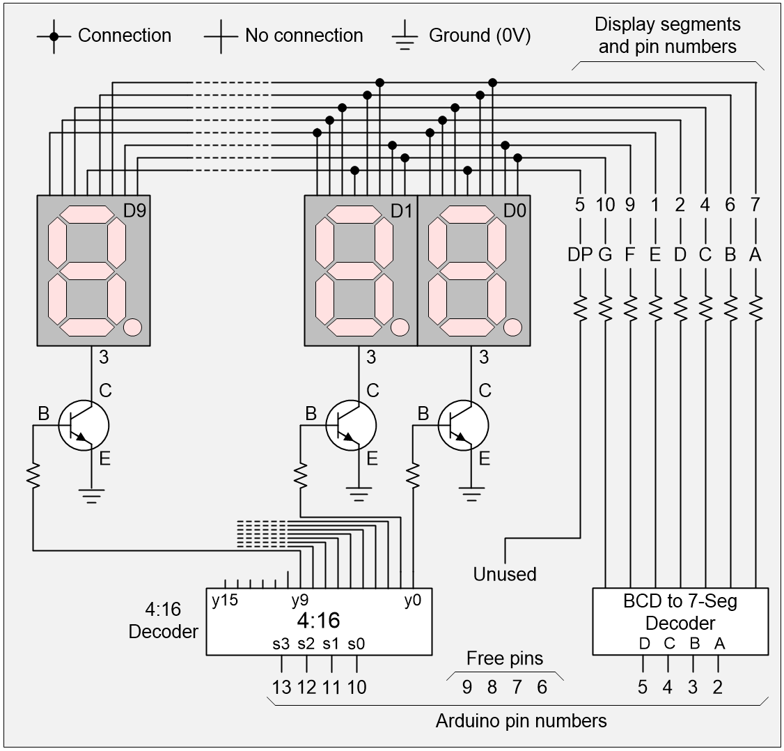
10 displays, 8 Arduino pins (Source: Max Maxfield)
OK, so we can currently control 10 displays using only 8 of the Arduino’s pins with only 2 additional ICs. Can we do better? You betcha! What we could do would be to replace our 4:16 decoder (which requires 4 pins to drive it) with a decoded binary decade counter.
“What’s a decoded binary decade counter?” I hear you cry. Well, a 4-bit binary counter passes through 16 states (0 to 15) as follows: 0000, 0001, 0010, 0011, 0100, 0101, 0110, 0111, 1000, 1001, 1010, 1011, 1100, 1101, 1110, 1111, and then back to 0000 again.
By comparison, a binary decade counter passes through only 10 states (0 to 9) as follows: 0000, 0001, 0010, 0011, 0100, 0101, 0110, 0111, 1000, 1001, and then back to 0000 again.
Finally, a decoded binary decade counter will take the output from the binary decade counter and decode it by setting one of its 10 output pins high: 1000000000, 0100000000, 0010000000, 0001000000, 0000100000, 0000010000, 0000000100, 0000000010, 0000000001, and then back to 100000000.
The point is that this decoded decade counter will require only two signals (pins) in the form of an initialize (INIT), which will place the counter in its initial 1000000000 state and a clock (CLK), which will increment it from one state to the next. This will leave us with 6 free pins while still requiring only 2 additional ICS as illustrated below.
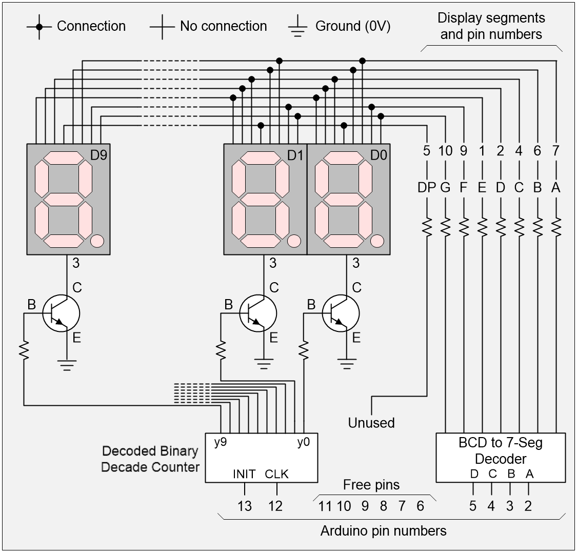
10 displays, 6 Arduino pins (Source: Max Maxfield)
As another aside, a lot of people will use a chain of 8-bit shift registers to control large numbers of 7-segment displays, and these certainly have their advantages, not least that we could reduce the total pin count to be as low as 4 (CLEAR, CLK, DATA, and LOAD) or even 3 (CLK, DATA, and LOAD) if we implement the equivalent of a CLR by shifting in a stream of 0s. Also, we would regain control of all our decimal points. The downside is that this would require us to use 10 extra chips (one 8-bit shift register per display) and—for the purposes of our problem—we are trying to use as few extra chips as possible. But we digress…
It’s possible to create a pure 4-bit binary ripple counter using only four flip-flops (usually T-type or JK-type) daisy-chained together such that the output of each flip-flop acts as the clock signal to the next higher-order flip-flop. It’s only the flop-flop representing the least-significant bit that’s fed by the main CLK signal from the outside world. The only problem with this counter is that it can take between 1 and 4 flip-flop delays for the new 4-bit count value to appear on the counter’s outputs.
Creating a binary decade counter is another marmite de poisson (“kettle of fish”). In this case, we will have to implement our counter as a finite state machine (FSM). The heart of our counter will be four D-type flip-flops, and we will decode the “next state” (the 4-bit value to load into the counter on the next clock) from the “current state” (the 4-bit value that’s currently stored in the counter).
And, of course, once we have our binary decade counter, we are still going to need to decode its outputs to generate the ten decoded binary decade counter values we require.
Is there any way to generate an equivalent of the decoded binary decade counter without having to go through the hassle of actually implementing and decoding a binary decade counter? Well, by golly, there is! For example, we can implement this in the form of a 10-bit ring counter, which is essentially a 10-bit shift register formed using D-type flip-flops, where the output from the final stage in the register chain is connected to the chain’s input as illustrated below:
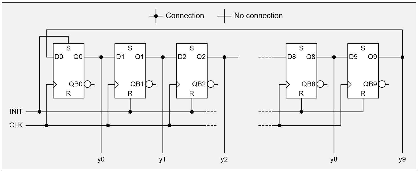
10-bit ring counter (Source: Max Maxfield)
This form of ring counter is called a straight ring counter or a one-hot ring counter. There’s another possibility. Rather than feeding back the true output from the last state, we can instead employ the complementary output, thereby resulting in a Johnson counter (also known as a twisted ring counter, a switch-tail ring counter, a walking ring counter, or a Möbius counter). This results in our circulating a stream of ones followed by zeros around the ring.
Just to keep things simple, let’s contrast and compare the sequences generated by a 5-stage straight ring counter (a) in the image below with a 5-stage Johnson counter (b) in the image below.
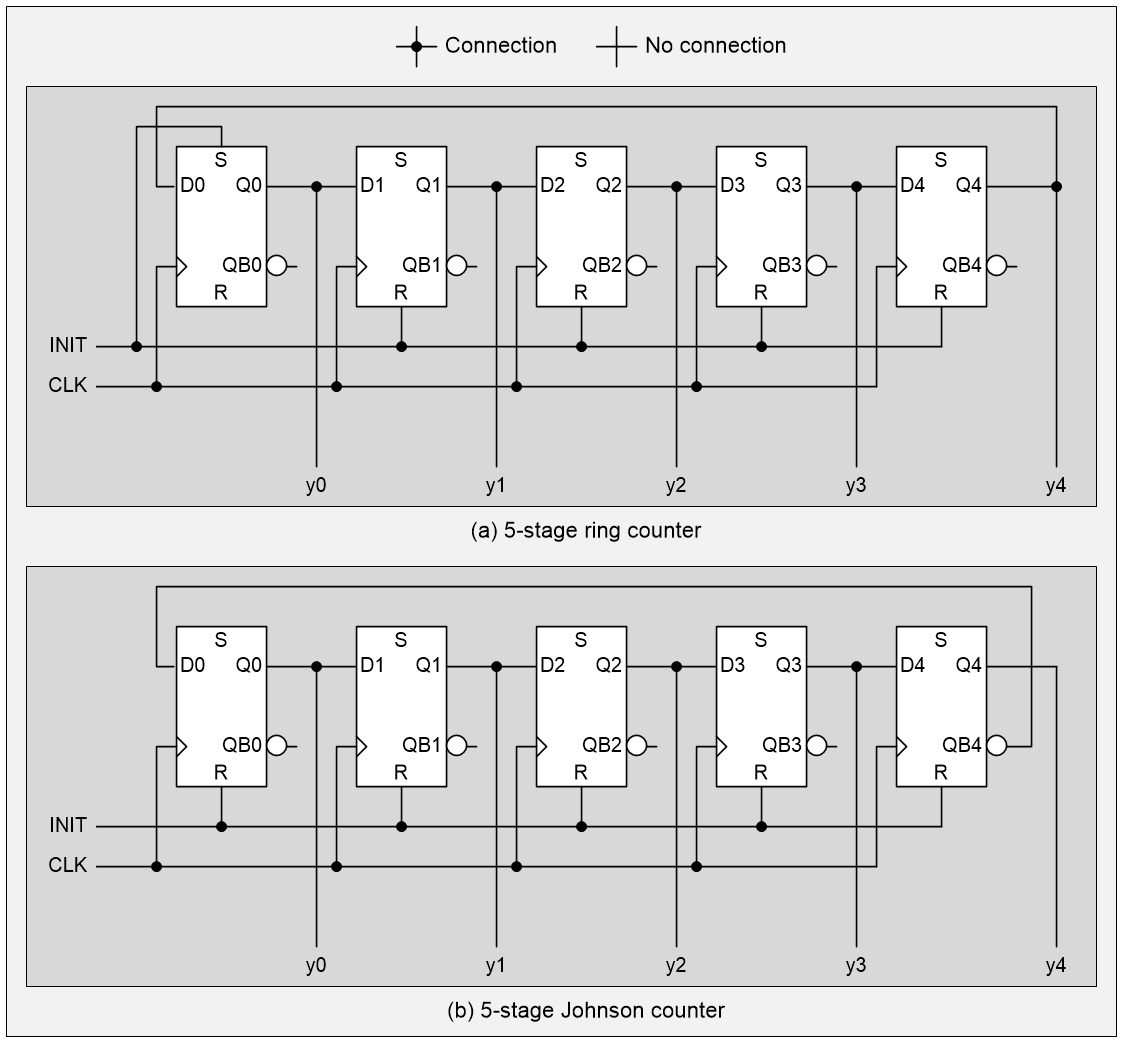
5-stage straight and Johnson ring counters (Source: Max Maxfield)
Observe that, in the case of the straight ring counter, the INIT signal drives the S (“set”) input to the first flip-flop and the R (“reset”) inputs to the remaining flip-flops. By comparison, in the case of the Johnson counter, the INIT signal drives the R inputs on all the flip-flops. The sequences resulting from these two implementations are as shown below.
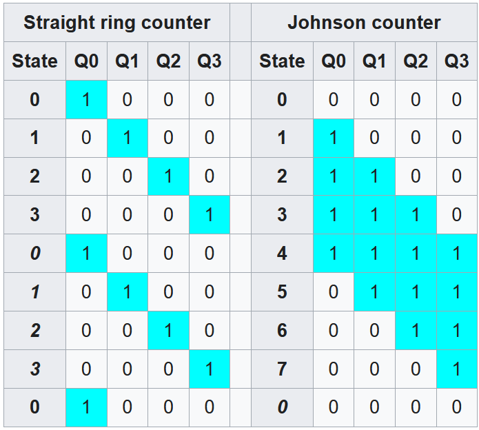
5-stage straight and Johnson ring counter state sequences (Source: Wikipedia)
In a crunchy nutshell, Johnson counters offer twice as many count states from the same number of shift registers. Also of interest is the fact that the Johnson counter generates a code in which adjacent states differ by only one bit as in a Gray code, which can be useful if the bit pattern is going to be asynchronously sampled.
When a fully decoded (one-hot representation) of the counter state is required, as in the case of driving our ten 7-segment displays, the straight ring counter presents these values by default. Happily, all that is required to decode the five outputs from a 5-stage Johnson counter into the ten 1-hot signals we require is to add ten 5-input AND gates (remember that we get the complementary outputs from our flip-flops for free). The result is known as a Johnson decade counter.
The core Johnson counter itself was invented by American inventor, engineer, computer pioneer, and professor, Robert Royce “Bob” Johnson. If your knee-jerk reaction is that Bob invented his counter in the desire to save transistors, you would be wrong because he wasn’t using transistors, which were horrendously expensive and not widely available at the time.
Bob’s counter was first described in a 1954 Patent. If you look at this patent, you will see that each of the register stages is implemented using two back-to-back vacuum tubes. So, rather than use 20 expensive vacuum tubes to implement a 10-stage straight ring counter, only 10 tubes were required to implement a 5-stage Johnson counter whose outputs could be decoded as required (a 5-input AND gate could be implemented using only 5 diodes and 1 resistor).
OK, so we know who invented the Johnson counter, but who invented the Johnson decade counter (that is, decoding the outputs from a 5-stage Johnson counter into ten 1-hot decade outputs)? I’ve not been able to find any evidence that Johnson did this himself. My suspicion is that some bright-spark engineer at TI or RCA saw a customer demand for a 1-hot decade counter and said, “I’ve got a good idea, let’s decode the output from a 5-stage Johnson counter and call the result a ‘Johnson decade counter.’”
If this is the case, my next question would be “Why?” Or, rather, “Why not just use a 10-stage straight ring counter and have done?” Based on what I said before, you may be thinking that a Johnson decade counter requires fewer transistors than a 10-stage straight ring counter, but I fear this is not the case. Take a CMOS implementation of a Johnson decade counter, for example. Let’s assume that a CMOS D-type flip-flop requires 20 transistors, so a 10-stage straight ring counter would require 10 x 20 = 200 transistors.
Now consider a CMOS Johnson decade counter like the CD74HC4017. In this case, we have only five D-type flip-flops, equating to 5 x 20 = 100 transistors. But we also require ten 5-input AND gates. Each input to a CMOS AND gate requires 2 transistors, so a 5-input AND will require 10 transistors, so ten 5-input ANDs will require 100 transistors, so our five flip-flops and ten 5-input AND gates will require a total of 200 transistors, which is the same as the straight rung counter, so why bother?
This is the sort of thing that keeps me up at nights LOL. How about you? Do you have any thoughts you’d care to share on any of this? As always, I welcome your insightful comments, penetrating questions, and sagacious suggestions.
Leave a Reply
You must be logged in to post a comment.